CBM-HD
What is it
CBM-HD is a project where a PC simulates one or more IEEE devices. If you are familiar with 64HDD, a PC simulating a 1541 drive, then you can consider CBM-HD as its IEEE equivalent.In 2000 I realized a connection between my CBM8032-SK and the LPT-port of my PC using my own XIEEE-cable. Originally it was planned to be able to support both the IEC and IEEE computers but due to some problems I encountered and lack of time, CBM-HD only supports the IEEE protocol for the moment.
The problems
The problems I encountered were all related to the fact that the CBM is much more time critical then the C64 is. To give you a good example, in PC-Disk 3 (an old project, not available anymore) I didn't collect the data for displaying the directory until the actual TALK command had been received. This process doesn't take much time, but according my 8032 too much: it timed out and displayed "?file not found"! This simply meant that I had to collect the data immediately after the initial command (just like a C= drive does).Much worse was the fact that the PC now and then failed somehow to notice that the CBM had activated the ATN line. On the end I was forced to add a bit of hardware that actually can be found in the real IEEE drives as well: a circuit that negates NRFD and NDAC as soon as ATN becomes low (called 'ATN trap' from now on).
The third problem: as you probably know, the difference between LOAD"$" and DIRECTORY is the fact that in the first case the data is stored as a program and in the second case is displayed directly on the screen. In the first case the data is sent as one file, in the second case the transfer is interrupted all the time by the CBM every one or more bytes. In this particular case the PC proofed to be too fast in sending bytes. The frustrating thing was that the CBM accepted the extra bytes but a debug session showed that it had not processed them. Inserting a delay of about 250 uSecs between each byte seems to solve this problem.
The above problem becomes even weirder with the PRINT# and GET# command: between each byte I have to wait up to 2 mSecs otherwise the CBM doesn't see them !!!
Features
- Multi-drive.
CBM-HD can emulate up to 8 devices if you want to. - Multi-disk format.
CBM-HD supports several formats including a kind of 4040/8250-compatible 16 MB hard disk drive. - Multi-OS.
CBM-HD supports the MS-DOS file system as well. But only the 8.3 naming convention can be used.
I also developed a CBM look-alike system: although using the DOS file system, it looks like a CBM one.
Disadvantages
CBM-HD is a simulator, not an emulator! It simulates the 4040 and some other drives only at the point of file handling. The commands Memory-Read and Memory-Write are supported but the memory area itself is not used by CBM-HD. Memory-Execute is not supported at all for the simple reason that a PC cannot run 6502 code.
Theory
If you forgot how IEEE-488 looked like, take a peek at my IEEE-document .IEEE has 16 active lines in total. All 16 can be either input, output or tristate. Eight of them are used for transferring data, the other eight for control. The state of each of the control lines depends on the fact what role the device is performing at the moment: a listener, a talker or a controller.
I copied one part of this document to make the next part more understandable:
Line         NRFD   NDAC   DAV    ATN    EOI    IFC    REN    SQR
             I  O | I  O | I  O | I  O | I  O | I  O | I  O | I  O |
-----------|------|------|------|------|------|------|------|------|
Listener   |    X |    X | X    | X    | X    | X    |      |      |
Talker     | X    | X    |    X | X    |    X | X    |      |      |
Controller | X  X | X  X | X  X | X  X | X  X |    X |    G | X    |
X marks line used as "I = Input" or "O = Output" The block Controller/REN is marked G because a CBM doesn't use this line. In this case it is hardware-wired to GROUND.
As you can see a device like a disk drive needs 4 input/output and 2 input lines. A computer needs 5 I/O, 1 output and 1 input line. Beside these lines, both need 8 bidirectional data lines of course. So the original idea was to use an LPT port as IEEE port. But due to the problems mentioned above, the ATN trap was needed and that's where the COM port comes in. This port delivers the output to control the extra hardware.
Remark: a second printer port does the job as well. For the moment I will only mention the COM port.
The hardware
What kind of PC do you need? I tested everything on a Pentium-1 75 MHz but I don't see any reason why it should not work on a 486 or 386. The program runs under DOS so 1 MB should do. Any PS/2 (also known as bidirectional), EPP or ECP printer port plus COM port should do.More practical would be a PC running Windows 98. Its real DOS mode can be used to run CBM-HD and the GUI mode can be used to exchange images and other files over ethernet.
Tip: if your main PC is running Windows 7, you either need a machine that is capable of running XP as well or you have to exchange the files with a PC with XP installed. AFAIK Windows 98 is NOT capable of sharing disks/directories with Windows 7.
As already said, a cable plus a bit of hardware is needed. And here I ran into a bit of trouble again. My first design works only in combination with the PS/2 printer port. But nowadays too many PCs only have an EPP and/or ECP port. So I expanded the actual design.
With my first design the PC could only act as device, not as controller. So I also wanted to add some 'goodies': active reset and active ATN. I first thought about dropping the first design but then a friend of mine persuaded me to publish all versions and leave the choice to you.
More versions mean more software. But in this case it is just adding an extra parameter and changing some subroutines. And I don't mind doing that. This kind of flexibility has another advantage: when another type of hardware is used, like a real IEEE port, chances are made quite easy.
Version 0
The very first version, version 0, was just a cable wired like this:
     LPT
 D-connector             IEEE
D0          2           1    D1
D1          3           2    D2
D2          4           3    D3
D3          5           4    D4
D4          6          13    D5
D5          7          14    D6
D6          8          15    D7
D7          9          16    D8
STROBE      1           5    EOI
AUTO FEED  14           6    DAV
INIT       16           7    NRFD
SELECT IN  17           8    NDAC
PAPER END  12           9    IFC (RESET)
ERROR      15          10    SRQ
ACKNWLDG   10          11    ATN
SELECT     13          17    REN
GND      18/25        18/24  GND
                       12    Shield
Version 1a
As mentioned before, after constantly getting unexplainable communication errors, I found out that an ATN trap was needed. This is a circuit found in the IEEE drives and does nothing else pulling NRFD and NDAC low the moment ATN becomes low. So I needed a circuit where ATN must be able to negate NDAC and NRFD but the PC must be able to disable this function (otherwise it would loose control of these lines the moment ATN is active). Only four 'Open Collector'-inverters and a pull-up resistor are needed.
Assume PC is (L). The moment ATN becomes (L), point(1) becomes (H), thus negating NDAC and NRFD.
Making PC (H) means that point (1) becomes (L) regardless of the state of ATN. in that case NDAC and NRFD can only be negated by the original outputs.
But what output is to be used for 'PC'? The specification of version 0 reveals that there is in fact no free output left to perform this function. But AFAIK almost every PC and laptop is also equipped with a COM-port that has at least three outputs. And one of them is going to be used; RTS in this case.

The reality:
The 7406 IC needs a +5 Volt supply in one or another way. This can be realized by extracting the power from the three RS232 outputs using diodes and a 78L05 voltage regulator.
Version 1b
I found out that some RS232 interfaces weren't able to supply enough power for the 7406. So I replaced the inverters by transistors.
Version 2
I found an original IBM serial/parallel card and realized the needed changes directly on the card including making it bidirectional. In this case I tapped the needed RTS signal directly from the output of the 8250/16450; no voltage conversion needed :)Advantage: as all circuits are inside the PC, only the cable of version 0 is needed. Looked a bit nicer too without all the extra external hardware :)
No schematic available because of the variety of cards. But if you are interested to alter such a card yourself, feel free to ask me about details.
FYI: I had a broken CBM 8050 disk drive, removed all its inner parts and inserted a PC motherboard, the card mentioned above and a hard disk drive. I was able to do it in such a way I even didn't need to drill extra holes :) I used the plastic fronts of two scrapped full size hard disk drives to fill the front holes of the CBM 8050. The IEEE connector of the unrepairable 8050 board completed the transformation.
Version 3: becoming a master
The RS232 port has three output ports from which I only used one so far. This gave me the idea to expand version 1b so it has an active ATN and IFC (= reset) signal as well. This enables my PC not only to act like an IEEE drive, but to control them as well.As you can see, SRQ and REN aren't present anymore; Commodore doesn't use them at all, so why should I?

So far I created images of a floppy by copying them sector by sector from a real drive to the PC using a CBM 8032. Now I could create them by reading the sectors directly from the drive instead.
Version 4:
My laptop has an EPP/ECP printer port that wouldn't cooperate with X1541 cable. That forced me to build a small X1541-to-XE1541 adapter. But this behaviour also meant that my XIEEE cable wouldn't work either. So I started to look for another solution that was found very quickly: using Scottky-diodes as used in the XE1541 cable, the X1541 variant meant for the EPP- and ECP-ports. The credits for this idea go to Nicolas Welte and Wolfgang Moser.But then Nicolas and Wolfgang informed me that they encountered systems where even their XE1541 cable didn't work properly; in this case one or more gates weren't able to sink enough current. So they developed the XA1541 cable where every Scottky-diode is replaced by a transistor and a resistor.
Using the transistors means we no longer have four bidirectional pins at our disposal and thus we need four extra inputs. On it self no problem, we still have a free one at the LPT-port and the COM-port can provide another four free inputs. But the use of these last ones requires some extra hardware because of the differences in the used voltage levels.
     LPT
 D-connector             IEEE
D0          2           1    D1
D1          3           2    D2
D2          4           3    D3
D3          5           4    D4
D4          6          13    D5
D5          7          14    D6
D6          8          15    D7
D7          9          16    D8

STROBE      1
BUSY       11           5    EOI

AUTO FEED  14
ERROR      15           8    NDAC

INIT       16
NO PAPER   12           7    NRFD

SELECT IN  17
SELECTED   13           6    DAV

GND      18/25        18/24  GND
                       12    Shield

RTS         7                enable ATN trap

ACKNWLDG   10          11    ATN
DTR         4

TxD         3           9    IFC (RESET)
DCD         1
As you can see the schematic: 
is based on version 3.

This schematic shows you the version I actually built: it is capable of handling IEC drives, like the 1541, as well!
Version 5: Two LPT ports
I just happened to run into some ISA cards with two bidirectional LPT ports onboard. The 7406 IC is still needed but that can be piggybacked on one of the existing ICs. This means:- eight output ports
- no voltage conversion needed
- no "ugly" external hardware needed
- the nice thing (for me) is that I can use the version 0 cable here as well.
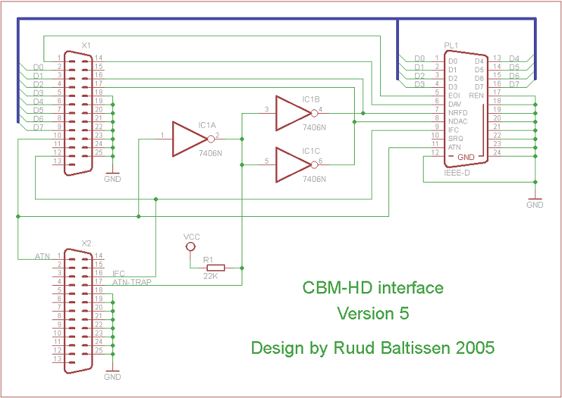
     LPT1
 D-connector             IEEE
D0          2           1    D1
D1          3           2    D2
D2          4           3    D3
D3          5           4    D4
D4          6          13    D5
D5          7          14    D6
D6          8          15    D7
D7          9          16    D8
STROBE      1           5    EOI
SELECT IN  17           6    DAV
INIT       16           7    NRFD
AUTO FEED  14           8    NDAC
PAPER END  12           9    IFC (RESET)
ERROR      15          10    SRQ
ACKNWLDG   10          11    ATN
SELECT     13          17    REN
GND      18/25        18/24  GND
                       12    Shield

     LPT2
 D-connector             IEEE
STROBE      1          11    ATN           -->  pin 10 of LPT1
SELECT IN  17           9    IFC (RESET)   -->  pin 12 of LPT1
INIT       16          enabling ATN trap
The flashing LED
Using my rebuilt 8050 I bumped into a quite stupid error: it had no screen. So what's the point you may think? The screen showed the errors the software encountered. As you know, the real 8050 will flash a LED when encountering an error. To blink a LED, I would need yet another output and again none were left. I could redesign the cable but had little interest in doing so, to be honest. Then I got the idea to use the speaker for this purpose. I replaced it with a resistor (150 Ohm) and a LED and this worked like a charm.The software
You can the executables for MS-DOS/W98-DOS, the sources and a D64 containing the Basic programs I used to test things by asking me.Important remark: the software only has been tested in real DOS mode; DOS 6.22 and Windows 98SE. And on forehand: I am not interested in making it run under Windows.
You can email me here.